Automated machining removes material under a programmed sequence of tool movements. In aerospace production, that sequence may use multi-axis CNC equipment, robotic tending, automated tool measurement or in-process probing. Those technologies can improve consistency and throughput, but they do not independently establish that a finished part meets every requirement. The useful question is not simply whether a machine ran; it is whether the production record connects the run to controlled inputs and meaningful verification.
Start with a defined part and route
Before cutting begins, the work order should identify the part, applicable drawing or model revision, material specification and planned operations. Revision control matters because a visually similar geometry may embody a changed tolerance, datum scheme or note. Material identity should remain linked to its lot or heat where that traceability is required by the contract or quality system. The route then identifies operation order, required checks and any special handling instructions.
That definition provides context for a machine program. A program name alone is weak evidence if it cannot be tied to the correct revision and approved change history. A controlled system can identify the released version, who authorized it, and whether edits are permitted at the machine. Where an operator selects a program or offset, the record should make the selection and verification steps understandable.
Make the setup part of the story
Fixtures locate and restrain stock so the machine can cut in a known relationship to its coordinate system. Their condition, clamping sequence and datum transfer can influence the final geometry. A setup sheet may define locating points, clamp positions, tool list, work offsets and first-piece checks. A robot loading a fixture adds another interface: gripping surfaces, orientation, part presence and seating need suitable controls. A cycle can repeat an incorrect setup just as consistently as a correct one.
Machine capability is conditional. Thermal state, spindle behavior, axis geometry, tool wear, cutting forces, coolant delivery and maintenance history can all affect results. Tool-life limits and breakage detection help manage change, but alarm-free operation is not proof of dimensional conformity. Likewise, an in-machine probe can identify certain conditions only if its calibration status, probe qualification, measurement routine and decision limits are controlled.
Control the cutting process
Tool selection, feeds, speeds and cutting strategy affect finish, heat and tool loading. The appropriate controls depend on material, geometry, machine and specification; a generic setting is not a production instruction. Recordkeeping may capture tool identity, usage limits, replacement events, program revision, machine identifier and any process interruptions relevant to quality. Not every datum must be retained forever; retention should follow applicable contractual, regulatory and quality-system requirements.
Robotic tending can reduce handling variation and keep equipment productive. It also introduces questions about gripper wear, loading orientation, interlocks, recovery after a fault and the safe return to cycle. A restart after interruption should not silently blur which operations were completed or which checks are due. Clear restart instructions and event records help establish what happened without assuming that automation makes judgment unnecessary.
Verify outcomes with a suitable method
Inspection planning translates drawing characteristics into measurement methods, sampling rules and acceptance criteria. Critical dimensions may require a coordinate measuring machine, a calibrated gauge or another method appropriate to the feature. A measurement result is meaningful only in relation to its datum reference, instrument capability, environmental conditions and uncertainty. Surface finish, burrs, edge conditions and visual defects may require different techniques from coordinate measurement.
A first-piece review can help validate a new setup or changed process, but its scope should be explicit. It does not mean every feature has been proven for all later production, nor does it replace required routine verification. When results are out of limits, preserve the original result, identify affected material and document the authorized disposition. Reworking a feature may change the inspection plan, so the record should identify the operation and the checks performed afterward.
Read the record as linked evidence
A strong machining record makes a practical chain visible: approved part definition, material identification, route, setup, machine and program state, tool controls, operation completion, inspection results and final disposition. Each link answers a different question. A machine log may show execution timing, while a quality record establishes acceptance decisions; neither should be mistaken for the other.
Standards such as ISO 9001 and AS9100 describe quality-management frameworks, while AS9102 addresses first article inspection requirements in applicable aerospace contexts. They are not substitutes for a drawing, purchase order or customer-specific obligation, and citing a standard does not establish that a particular supplier or part is certified. Applicable revision, scope and contractual use must be checked by the responsible organization. The objective here is disciplined interpretation: distinguish process capability from inspection evidence, and both from formal qualification.
For readers reviewing a machining package, begin with identity and revision, then follow the route through setup and operation records to the actual inspection results. Ask how deviations were controlled and whether the final decision was made by an authorized role. That approach keeps the focus on evidence tied to the part, rather than a machine's reputation or a general claim of precision.
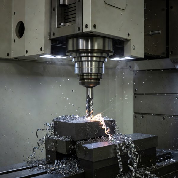

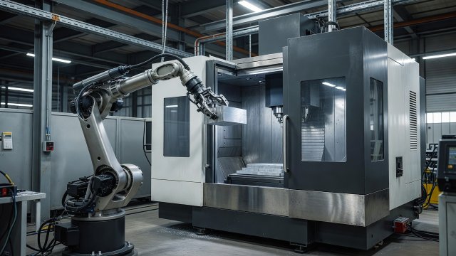
Generic industrial photography; these images do not document a verified aircraft component or production line.